
discuss@lists.openscad.org

OpenSCAD general discussion Mailing-list

View all threads

Unexpected behavior

ME
Mark Erbaugh
Fri, Apr 17, 2026 1:06 AM

I’m able to see the same thing. Looking at the gap as I zoom in, I suspect it is caused by rounding errors in the calculation.

On Apr 16, 2026, at 5:05 PM, Jordan Brown openscad@jordan.maileater.net wrote:

On 4/16/2026 2:01 PM, Jordan Brown via Discuss wrote:

But I looked at your OpenSCAD model closely, looking only at one invocation of shield(), and if you look really closely you see a very small gap between the colors, at least for curved boundaries.  Exactly where that gap comes from, I don't know.

Here's an example.  I put an ! in front of shield(base_height) so that I got just that, and then zoomed way, way in, in orthogonal mode viewing from +Z.  The distance shown in the status bar was 0.09.

<EEl60drhazRwS8Ql.png>

I’m able to see the same thing. Looking at the gap as I zoom in, I suspect it is caused by rounding errors in the calculation. > On Apr 16, 2026, at 5:05 PM, Jordan Brown <openscad@jordan.maileater.net> wrote: > > On 4/16/2026 2:01 PM, Jordan Brown via Discuss wrote: >> But I looked at your OpenSCAD model closely, looking only at one invocation of shield(), and if you look really closely you see a very small gap between the colors, at least for curved boundaries. Exactly where that gap comes from, I don't know. > > Here's an example. I put an ! in front of shield(base_height) so that I got just that, and then zoomed way, way in, in orthogonal mode viewing from +Z. The distance shown in the status bar was 0.09. > > <EEl60drhazRwS8Ql.png>
ME
Mark Erbaugh
Fri, Apr 17, 2026 1:07 AM

I’m not sure what you mean by cloning the geometry.

Mark

It’s probably an artifact of the way I created the .SVG file. While developing it, I noticed a couple of  larger gaps
and was able to edit them out. 0.0002 mm might be so small that I can’t see it even with maximum zoom in Affinity Designer.

It would be appropriate to clone the geometry in question and export the cloned geometry of each region to ensure each instance is consistent.

I’m not sure what you mean by cloning the geometry. Mark > >> It’s probably an artifact of the way I created the .SVG file. While developing it, I noticed a couple of larger gaps >> and was able to edit them out. 0.0002 mm might be so small that I can’t see it even with maximum zoom in Affinity Designer. > > It would be appropriate to clone the geometry in question and export the cloned geometry of each region to ensure each instance is consistent. >
ME
Mark Erbaugh
Fri, Apr 17, 2026 1:10 AM

I suspect you are correct. Even with the gaps that Jordan pointed out, the slicer had no issues.  The problem I had at the beginning was due to a significantly larger (yet still small) gap in the .svg file. It was on the order of the layer width (0.4mm).

Mark

On Apr 16, 2026, at 7:30 PM, Jon Bondy via Discuss discuss@lists.openscad.org wrote:

In my experience, fluctuations in geometry that are much smaller than 0.050 mm are basically ignored by most slicers.

I suspect you are correct. Even with the gaps that Jordan pointed out, the slicer had no issues. The problem I had at the beginning was due to a significantly larger (yet still small) gap in the .svg file. It was on the order of the layer width (0.4mm). Mark > On Apr 16, 2026, at 7:30 PM, Jon Bondy via Discuss <discuss@lists.openscad.org> wrote: > > In my experience, fluctuations in geometry that are much smaller than 0.050 mm are basically ignored by most slicers. >
WF
William F. Adams
Fri, Apr 17, 2026 1:42 AM

On Thursday, April 16, 2026 at 09:07:15 PM EDT, Mark Erbaugh mark.election@gmail.com wrote:

I’m not sure what you mean by cloning the geometry.

Probably easier to create one file which has all the geometry in it with no redundancy, save it, copy it once for each colour, open each copy, delete the geometry which is not needed for that colour, save.

Alternately, create said file w/ all non-redundant geometry, make a layer for each colour, clone each element in place/registration, move the copies to the new layer, join everyone on each layer, then export each layer as a separate file.

William

On Thursday, April 16, 2026 at 09:07:15 PM EDT, Mark Erbaugh <mark.election@gmail.com> wrote: >I’m not sure what you mean by cloning the geometry. Probably easier to create one file which has all the geometry in it with no redundancy, save it, copy it once for each colour, open each copy, delete the geometry which is not needed for that colour, save. Alternately, create said file w/ all non-redundant geometry, make a layer for each colour, clone each element in place/registration, move the copies to the new layer, join everyone on each layer, then export each layer as a separate file. William
TA
Todd Allen
Mon, Apr 20, 2026 3:04 AM

I often place cuts of 0.001mm in my models to direct the extrusion path of
perimeters in and out of a model's interior instead of the default
behaviour of just going around the outer circumference.  There are
parameters for resolution and closing gaps that must be set to enable the
fine cuts to work.

On Thu, Apr 16, 2026, 6:31 PM Jon Bondy via Discuss <
discuss@lists.openscad.org> wrote:

In my experience, fluctuations in geometry that are much smaller than
0.050 mm are basically ignored by most slicers.

Jon

On 4/16/2026 7:23 PM, William F. Adams via Discuss wrote:

On Thursday, April 16, 2026 at 04:45:27 PM EDT, Mark Erbaugh <

Thanks for looking into that. That probably explains things. Affinity

Designer is designed for creating print materials

and that small gap probably doesn’t matter for that.

That gap would absolutely matter for printing, precluding any sort of

automated trapping from working.

William


OpenSCAD mailing list
To unsubscribe send an email to discuss-leave@lists.openscad.org

--
This email has been checked for viruses by AVG antivirus software.
www.avg.com


OpenSCAD mailing list
To unsubscribe send an email to discuss-leave@lists.openscad.org

I often place cuts of 0.001mm in my models to direct the extrusion path of perimeters in and out of a model's interior instead of the default behaviour of just going around the outer circumference. There are parameters for resolution and closing gaps that must be set to enable the fine cuts to work. On Thu, Apr 16, 2026, 6:31 PM Jon Bondy via Discuss < discuss@lists.openscad.org> wrote: > In my experience, fluctuations in geometry that are much smaller than > 0.050 mm are basically ignored by most slicers. > > Jon > > > On 4/16/2026 7:23 PM, William F. Adams via Discuss wrote: > > On Thursday, April 16, 2026 at 04:45:27 PM EDT, Mark Erbaugh < > mark.election@gmail.com> wrote: > > > >> Thanks for looking into that. That probably explains things. Affinity > Designer is designed for creating print materials > >> and that small gap probably doesn’t matter for that. > > That gap would absolutely matter for printing, precluding any sort of > automated trapping from working. > > > > William > > _______________________________________________ > > OpenSCAD mailing list > > To unsubscribe send an email to discuss-leave@lists.openscad.org > > -- > This email has been checked for viruses by AVG antivirus software. > www.avg.com > _______________________________________________ > OpenSCAD mailing list > To unsubscribe send an email to discuss-leave@lists.openscad.org
JJ
jon jonbondy.com
Mon, Apr 20, 2026 11:35 AM

I would be curious to see an example of this.

Jon

On 4/19/2026 11:04 PM, Todd Allen wrote:
I often place cuts of 0.001mm in my models to direct the extrusion path of perimeters in and out of a model's interior instead of the default behaviour of just going around the outer circumference.  There are parameters for resolution and closing gaps that must be set to enable the fine cuts to work.

On Thu, Apr 16, 2026, 6:31 PM Jon Bondy via Discuss <discuss@lists.openscad.orgmailto:discuss@lists.openscad.org> wrote:
In my experience, fluctuations in geometry that are much smaller than
0.050 mm are basically ignored by most slicers.

Jon
I would be curious to see an example of this. Jon On 4/19/2026 11:04 PM, Todd Allen wrote: I often place cuts of 0.001mm in my models to direct the extrusion path of perimeters in and out of a model's interior instead of the default behaviour of just going around the outer circumference. There are parameters for resolution and closing gaps that must be set to enable the fine cuts to work. On Thu, Apr 16, 2026, 6:31 PM Jon Bondy via Discuss <discuss@lists.openscad.org<mailto:discuss@lists.openscad.org>> wrote: In my experience, fluctuations in geometry that are much smaller than 0.050 mm are basically ignored by most slicers. Jon
TA
Todd Allen
Mon, Apr 20, 2026 2:47 PM

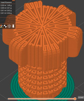
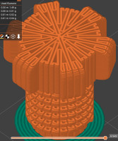
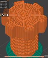
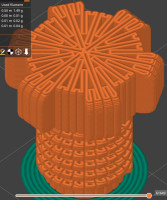
Here's a threaded fastener greatly strengthened with radial cuts sliced in
vase mode.
[image: vasecoresliced.jpg]

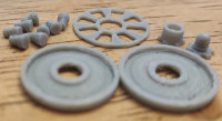
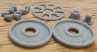
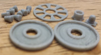
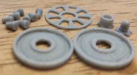
Here are the parts for a cartridge axial roller bearing 16 mm diameter by 4
mm diameter thickness.  The threaded fastener with a 2.5 mm diameter was
printed on a cheap fdm printer with a 0.4 mm nozzle using this technique.
[image: arb 4mm parts.jpg]

On Mon, Apr 20, 2026 at 6:35 AM jon jonbondy.com jon@jonbondy.com wrote:

I would be curious to see an example of this.

Jon
On 4/19/2026 11:04 PM, Todd Allen wrote:

I often place cuts of 0.001mm in my models to direct the extrusion path of
perimeters in and out of a model's interior instead of the default
behaviour of just going around the outer circumference.  There are
parameters for resolution and closing gaps that must be set to enable the
fine cuts to work.

On Thu, Apr 16, 2026, 6:31 PM Jon Bondy via Discuss <
discuss@lists.openscad.org> wrote:

In my experience, fluctuations in geometry that are much smaller than
0.050 mm are basically ignored by most slicers.

Jon
Here's a threaded fastener greatly strengthened with radial cuts sliced in vase mode. [image: vasecoresliced.jpg] Here are the parts for a cartridge axial roller bearing 16 mm diameter by 4 mm diameter thickness. The threaded fastener with a 2.5 mm diameter was printed on a cheap fdm printer with a 0.4 mm nozzle using this technique. [image: arb 4mm parts.jpg] On Mon, Apr 20, 2026 at 6:35 AM jon jonbondy.com <jon@jonbondy.com> wrote: > I would be curious to see an example of this. > > Jon > On 4/19/2026 11:04 PM, Todd Allen wrote: > > I often place cuts of 0.001mm in my models to direct the extrusion path of > perimeters in and out of a model's interior instead of the default > behaviour of just going around the outer circumference. There are > parameters for resolution and closing gaps that must be set to enable the > fine cuts to work. > > On Thu, Apr 16, 2026, 6:31 PM Jon Bondy via Discuss < > discuss@lists.openscad.org> wrote: > >> In my experience, fluctuations in geometry that are much smaller than >> 0.050 mm are basically ignored by most slicers. >> >> Jon >> >>
JJ
jon jonbondy.com
Mon, Apr 20, 2026 3:02 PM

Ah.  Vase Mode.  Now that makes sense.

Does it help with "regular" prints?

On 4/20/2026 10:47 AM, Todd Allen wrote:
Here's a threaded fastener greatly strengthened with radial cuts sliced in vase mode.
[vasecoresliced.jpg]

Here are the parts for a cartridge axial roller bearing 16 mm diameter by 4 mm diameter thickness.  The threaded fastener with a 2.5 mm diameter was printed on a cheap fdm printer with a 0.4 mm nozzle using this technique.
[arb 4mm parts.jpg]

On Mon, Apr 20, 2026 at 6:35 AM jon jonbondy.comhttps://urldefense.proofpoint.com/v2/url?u=http-3A__jonbondy.com&d=DwMFaQ&c=euGZstcaTDllvimEN8b7jXrwqOf-v5A_CdpgnVfiiMM&r=AsrE-c7ZR7B2Kyr3qgfvvppkCEBVsNmwEMndcrRSuOI&m=He3_BA298J18i99k3_jr_gmsoCm5sI9QBqr-Pvp2aAeXHDj_nSCsntZvh8-KEXQj&s=hMI3xQqYW9gmcrE3_slw495ZxkDcSbJJB9FeQLUVUoM&e= <jon@jonbondy.commailto:jon@jonbondy.com> wrote:

I would be curious to see an example of this.

Jon

On 4/19/2026 11:04 PM, Todd Allen wrote:
I often place cuts of 0.001mm in my models to direct the extrusion path of perimeters in and out of a model's interior instead of the default behaviour of just going around the outer circumference.  There are parameters for resolution and closing gaps that must be set to enable the fine cuts to work.

On Thu, Apr 16, 2026, 6:31 PM Jon Bondy via Discuss <discuss@lists.openscad.orgmailto:discuss@lists.openscad.org> wrote:
In my experience, fluctuations in geometry that are much smaller than
0.050 mm are basically ignored by most slicers.

Jon
Ah. Vase Mode. Now that makes sense. Does it help with "regular" prints? On 4/20/2026 10:47 AM, Todd Allen wrote: Here's a threaded fastener greatly strengthened with radial cuts sliced in vase mode. [vasecoresliced.jpg] Here are the parts for a cartridge axial roller bearing 16 mm diameter by 4 mm diameter thickness. The threaded fastener with a 2.5 mm diameter was printed on a cheap fdm printer with a 0.4 mm nozzle using this technique. [arb 4mm parts.jpg] On Mon, Apr 20, 2026 at 6:35 AM jon jonbondy.com<https://urldefense.proofpoint.com/v2/url?u=http-3A__jonbondy.com&d=DwMFaQ&c=euGZstcaTDllvimEN8b7jXrwqOf-v5A_CdpgnVfiiMM&r=AsrE-c7ZR7B2Kyr3qgfvvppkCEBVsNmwEMndcrRSuOI&m=He3_BA298J18i99k3_jr_gmsoCm5sI9QBqr-Pvp2aAeXHDj_nSCsntZvh8-KEXQj&s=hMI3xQqYW9gmcrE3_slw495ZxkDcSbJJB9FeQLUVUoM&e=> <jon@jonbondy.com<mailto:jon@jonbondy.com>> wrote: I would be curious to see an example of this. Jon On 4/19/2026 11:04 PM, Todd Allen wrote: I often place cuts of 0.001mm in my models to direct the extrusion path of perimeters in and out of a model's interior instead of the default behaviour of just going around the outer circumference. There are parameters for resolution and closing gaps that must be set to enable the fine cuts to work. On Thu, Apr 16, 2026, 6:31 PM Jon Bondy via Discuss <discuss@lists.openscad.org<mailto:discuss@lists.openscad.org>> wrote: In my experience, fluctuations in geometry that are much smaller than 0.050 mm are basically ignored by most slicers. Jon
TA
Todd Allen
Mon, Apr 20, 2026 3:11 PM

Yes, controlling extrusion paths can improve many issues such as overhangs,
bridges, bed adhesion and warping, surface quality, precision of exteriors
and interior holes, achieving greater strength with fewer perimeters and
less infill, etc.

On Mon, Apr 20, 2026 at 10:02 AM jon jonbondy.com jon@jonbondy.com wrote:

Ah.  Vase Mode.  Now that makes sense.

Does it help with "regular" prints?

On 4/20/2026 10:47 AM, Todd Allen wrote:

Here's a threaded fastener greatly strengthened with radial cuts sliced in
vase mode.
[image: vasecoresliced.jpg]

Here are the parts for a cartridge axial roller bearing 16 mm diameter by
4 mm diameter thickness.  The threaded fastener with a 2.5 mm diameter was
printed on a cheap fdm printer with a 0.4 mm nozzle using this technique.
[image: arb 4mm parts.jpg]

On Mon, Apr 20, 2026 at 6:35 AM jon jonbondy.com
https://urldefense.proofpoint.com/v2/url?u=http-3A__jonbondy.com&d=DwMFaQ&c=euGZstcaTDllvimEN8b7jXrwqOf-v5A_CdpgnVfiiMM&r=AsrE-c7ZR7B2Kyr3qgfvvppkCEBVsNmwEMndcrRSuOI&m=He3_BA298J18i99k3_jr_gmsoCm5sI9QBqr-Pvp2aAeXHDj_nSCsntZvh8-KEXQj&s=hMI3xQqYW9gmcrE3_slw495ZxkDcSbJJB9FeQLUVUoM&e=
jon@jonbondy.com wrote:

I would be curious to see an example of this.

Jon
On 4/19/2026 11:04 PM, Todd Allen wrote:

I often place cuts of 0.001mm in my models to direct the extrusion path
of perimeters in and out of a model's interior instead of the default
behaviour of just going around the outer circumference.  There are
parameters for resolution and closing gaps that must be set to enable the
fine cuts to work.

On Thu, Apr 16, 2026, 6:31 PM Jon Bondy via Discuss <
discuss@lists.openscad.org> wrote:

In my experience, fluctuations in geometry that are much smaller than
0.050 mm are basically ignored by most slicers.

Jon
Yes, controlling extrusion paths can improve many issues such as overhangs, bridges, bed adhesion and warping, surface quality, precision of exteriors and interior holes, achieving greater strength with fewer perimeters and less infill, etc. On Mon, Apr 20, 2026 at 10:02 AM jon jonbondy.com <jon@jonbondy.com> wrote: > Ah. Vase Mode. Now that makes sense. > > Does it help with "regular" prints? > > > On 4/20/2026 10:47 AM, Todd Allen wrote: > > Here's a threaded fastener greatly strengthened with radial cuts sliced in > vase mode. > [image: vasecoresliced.jpg] > > Here are the parts for a cartridge axial roller bearing 16 mm diameter by > 4 mm diameter thickness. The threaded fastener with a 2.5 mm diameter was > printed on a cheap fdm printer with a 0.4 mm nozzle using this technique. > [image: arb 4mm parts.jpg] > > On Mon, Apr 20, 2026 at 6:35 AM jon jonbondy.com > <https://urldefense.proofpoint.com/v2/url?u=http-3A__jonbondy.com&d=DwMFaQ&c=euGZstcaTDllvimEN8b7jXrwqOf-v5A_CdpgnVfiiMM&r=AsrE-c7ZR7B2Kyr3qgfvvppkCEBVsNmwEMndcrRSuOI&m=He3_BA298J18i99k3_jr_gmsoCm5sI9QBqr-Pvp2aAeXHDj_nSCsntZvh8-KEXQj&s=hMI3xQqYW9gmcrE3_slw495ZxkDcSbJJB9FeQLUVUoM&e=> > <jon@jonbondy.com> wrote: > >> I would be curious to see an example of this. >> >> Jon >> On 4/19/2026 11:04 PM, Todd Allen wrote: >> >> I often place cuts of 0.001mm in my models to direct the extrusion path >> of perimeters in and out of a model's interior instead of the default >> behaviour of just going around the outer circumference. There are >> parameters for resolution and closing gaps that must be set to enable the >> fine cuts to work. >> >> On Thu, Apr 16, 2026, 6:31 PM Jon Bondy via Discuss < >> discuss@lists.openscad.org> wrote: >> >>> In my experience, fluctuations in geometry that are much smaller than >>> 0.050 mm are basically ignored by most slicers. >>> >>> Jon >>> >>>
JJ
jon jonbondy.com
Mon, Apr 20, 2026 3:27 PM

Again, an example or two would be appreciated.

On 4/20/2026 11:11 AM, Todd Allen wrote:
Yes, controlling extrusion paths can improve many issues such as overhangs, bridges, bed adhesion and warping, surface quality, precision of exteriors and interior holes, achieving greater strength with fewer perimeters and less infill, etc.

On Mon, Apr 20, 2026 at 10:02 AM jon jonbondy.comhttps://urldefense.proofpoint.com/v2/url?u=http-3A__jonbondy.com&d=DwMFaQ&c=euGZstcaTDllvimEN8b7jXrwqOf-v5A_CdpgnVfiiMM&r=AsrE-c7ZR7B2Kyr3qgfvvppkCEBVsNmwEMndcrRSuOI&m=kkN6fnGviqF3MRb6QsdfriHn4y2GYLzBWNgkX1ft8UpkzAxAIRhQlVBozniRO3T0&s=xseYRy_0NaxGLy8Tn5HB-EW1ZMCHvnDvb8eviGKYuag&e= <jon@jonbondy.commailto:jon@jonbondy.com> wrote:

Ah.  Vase Mode.  Now that makes sense.

Does it help with "regular" prints?

On 4/20/2026 10:47 AM, Todd Allen wrote:
Here's a threaded fastener greatly strengthened with radial cuts sliced in vase mode.
[vasecoresliced.jpg]

Here are the parts for a cartridge axial roller bearing 16 mm diameter by 4 mm diameter thickness.  The threaded fastener with a 2.5 mm diameter was printed on a cheap fdm printer with a 0.4 mm nozzle using this technique.
[arb 4mm parts.jpg]

On Mon, Apr 20, 2026 at 6:35 AM jon jonbondy.comhttps://urldefense.proofpoint.com/v2/url?u=http-3A__jonbondy.com&d=DwMFaQ&c=euGZstcaTDllvimEN8b7jXrwqOf-v5A_CdpgnVfiiMM&r=AsrE-c7ZR7B2Kyr3qgfvvppkCEBVsNmwEMndcrRSuOI&m=He3_BA298J18i99k3_jr_gmsoCm5sI9QBqr-Pvp2aAeXHDj_nSCsntZvh8-KEXQj&s=hMI3xQqYW9gmcrE3_slw495ZxkDcSbJJB9FeQLUVUoM&e= <jon@jonbondy.commailto:jon@jonbondy.com> wrote:

I would be curious to see an example of this.

Jon

On 4/19/2026 11:04 PM, Todd Allen wrote:
I often place cuts of 0.001mm in my models to direct the extrusion path of perimeters in and out of a model's interior instead of the default behaviour of just going around the outer circumference.  There are parameters for resolution and closing gaps that must be set to enable the fine cuts to work.

On Thu, Apr 16, 2026, 6:31 PM Jon Bondy via Discuss <discuss@lists.openscad.orgmailto:discuss@lists.openscad.org> wrote:
In my experience, fluctuations in geometry that are much smaller than
0.050 mm are basically ignored by most slicers.

Jon
Again, an example or two would be appreciated. On 4/20/2026 11:11 AM, Todd Allen wrote: Yes, controlling extrusion paths can improve many issues such as overhangs, bridges, bed adhesion and warping, surface quality, precision of exteriors and interior holes, achieving greater strength with fewer perimeters and less infill, etc. On Mon, Apr 20, 2026 at 10:02 AM jon jonbondy.com<https://urldefense.proofpoint.com/v2/url?u=http-3A__jonbondy.com&d=DwMFaQ&c=euGZstcaTDllvimEN8b7jXrwqOf-v5A_CdpgnVfiiMM&r=AsrE-c7ZR7B2Kyr3qgfvvppkCEBVsNmwEMndcrRSuOI&m=kkN6fnGviqF3MRb6QsdfriHn4y2GYLzBWNgkX1ft8UpkzAxAIRhQlVBozniRO3T0&s=xseYRy_0NaxGLy8Tn5HB-EW1ZMCHvnDvb8eviGKYuag&e=> <jon@jonbondy.com<mailto:jon@jonbondy.com>> wrote: Ah. Vase Mode. Now that makes sense. Does it help with "regular" prints? On 4/20/2026 10:47 AM, Todd Allen wrote: Here's a threaded fastener greatly strengthened with radial cuts sliced in vase mode. [vasecoresliced.jpg] Here are the parts for a cartridge axial roller bearing 16 mm diameter by 4 mm diameter thickness. The threaded fastener with a 2.5 mm diameter was printed on a cheap fdm printer with a 0.4 mm nozzle using this technique. [arb 4mm parts.jpg] On Mon, Apr 20, 2026 at 6:35 AM jon jonbondy.com<https://urldefense.proofpoint.com/v2/url?u=http-3A__jonbondy.com&d=DwMFaQ&c=euGZstcaTDllvimEN8b7jXrwqOf-v5A_CdpgnVfiiMM&r=AsrE-c7ZR7B2Kyr3qgfvvppkCEBVsNmwEMndcrRSuOI&m=He3_BA298J18i99k3_jr_gmsoCm5sI9QBqr-Pvp2aAeXHDj_nSCsntZvh8-KEXQj&s=hMI3xQqYW9gmcrE3_slw495ZxkDcSbJJB9FeQLUVUoM&e=> <jon@jonbondy.com<mailto:jon@jonbondy.com>> wrote: I would be curious to see an example of this. Jon On 4/19/2026 11:04 PM, Todd Allen wrote: I often place cuts of 0.001mm in my models to direct the extrusion path of perimeters in and out of a model's interior instead of the default behaviour of just going around the outer circumference. There are parameters for resolution and closing gaps that must be set to enable the fine cuts to work. On Thu, Apr 16, 2026, 6:31 PM Jon Bondy via Discuss <discuss@lists.openscad.org<mailto:discuss@lists.openscad.org>> wrote: In my experience, fluctuations in geometry that are much smaller than 0.050 mm are basically ignored by most slicers. Jon