

discuss@lists.openscad.org

OpenSCAD general discussion Mailing-list

View all threads

Unexpected behavior

ME
Mark Erbaugh
Thu, Apr 16, 2026 2:11 PM

I’m seeing something strange. I think I know what’s going on, but I want to hear from the experts.

I used Affinity Designer to create a four color logo and separate it into four .svg files, one for each color.

I import these four .svg files into OpenSCAD color and extrude them all the same height then create a union and translate up by the height of the base (see below). This is the top, colored layers of my object.

I do the same import with a different height and change the color of the entire union to the background color. This is the base of my logo object.

I then export the union of these two as a .3mf file into my slicer (Bambu Studio).

When I slice the object, inside the base portion which should be a solid color, I see inclusions. I don’t see any relationship between these inclusions and items in my .svg files. I’ve examined the .svg files and don’t see anything in there, although I could be missing something. The inclusions appear differently on different layers, so if it were an error in the ,svg file, I would think the inclusion would be at the same location on every layer.

If I do a hull on the base object, the inclusions go away.

Is this a rendering issue where rounding causes small gaps between the separate color .svg curves or something else.

Mark

I’m seeing something strange. I think I know what’s going on, but I want to hear from the experts. I used Affinity Designer to create a four color logo and separate it into four .svg files, one for each color. I import these four .svg files into OpenSCAD color and extrude them all the same height then create a union and translate up by the height of the base (see below). This is the top, colored layers of my object. I do the same import with a different height and change the color of the entire union to the background color. This is the base of my logo object. I then export the union of these two as a .3mf file into my slicer (Bambu Studio). When I slice the object, inside the base portion which should be a solid color, I see inclusions. I don’t see any relationship between these inclusions and items in my .svg files. I’ve examined the .svg files and don’t see anything in there, although I could be missing something. The inclusions appear differently on different layers, so if it were an error in the ,svg file, I would think the inclusion would be at the same location on every layer. If I do a hull on the base object, the inclusions go away. Is this a rendering issue where rounding causes small gaps between the separate color .svg curves or something else. Mark
JB
Jordan Brown
Thu, Apr 16, 2026 4:16 PM

Your theory that there are micro gaps between the SVG images certainly
seems plausible.  Exactly where in the pipeline they might have come
from ... who knows.

It's not terribly surprising that they would vary from layer to layer,
because the Z component of the extrusion is triangles connecting points
on the bottom to points on the top, and those are not going to be
straight lines.

Given the data files we could look closer.  My first step would be to
take the SVGs, import them all into Inkscape, and look at them with a
microscope.

Your theory that there are micro gaps between the SVG images certainly seems plausible.  Exactly where in the pipeline they might have come from ... who knows. It's not terribly surprising that they would vary from layer to layer, because the Z component of the extrusion is triangles connecting points on the bottom to points on the top, and those are not going to be straight lines. Given the data files we could look closer.  My first step would be to take the SVGs, import them all into Inkscape, and look at them with a microscope.
ME
Mark Erbaugh
Thu, Apr 16, 2026 4:36 PM

Here is the OpenSCAD file and the .svg files.

On Apr 16, 2026, at 12:16 PM, Jordan Brown openscad@jordan.maileater.net wrote:

Your theory that there are micro gaps between the SVG images certainly seems plausible.  Exactly where in the pipeline they might have come from ... who knows.

It's not terribly surprising that they would vary from layer to layer, because the Z component of the extrusion is triangles connecting points on the bottom to points on the top, and those are not going to be straight lines.

Given the data files we could look closer.  My first step would be to take the SVGs, import them all into Inkscape, and look at them with a microscope.

Here is the OpenSCAD file and the .svg files. > On Apr 16, 2026, at 12:16 PM, Jordan Brown <openscad@jordan.maileater.net> wrote: > > Your theory that there are micro gaps between the SVG images certainly seems plausible. Exactly where in the pipeline they might have come from ... who knows. > > It's not terribly surprising that they would vary from layer to layer, because the Z component of the extrusion is triangles connecting points on the bottom to points on the top, and those are not going to be straight lines. > > Given the data files we could look closer. My first step would be to take the SVGs, import them all into Inkscape, and look at them with a microscope.
WF
William F. Adams
Thu, Apr 16, 2026 7:26 PM

There looks to be ~0.002mm of gap in the first region I checked:

William
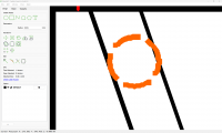
There looks to be ~0.002mm of gap in the first region I checked: William
ME
Mark Erbaugh
Thu, Apr 16, 2026 8:32 PM

Thanks for looking into that. That probably explains things. Affinity Designer is designed for creating print materials and that small gap probably doesn’t matter for that.

It’s probably an artifact of the way I created the .SVG file. While developing it, I noticed a couple of  larger gaps and was able to edit them out. 0.0002 mm might be so small that I can’t see it even with maximum zoom in Affinity Designer.

I’m not an expert with Affinity Designer, but I’ll play with it some more to see if there is a way to remove these gaps.

Thanks again,
Mark

On Apr 16, 2026, at 3:26 PM, William F. Adams via Discuss discuss@lists.openscad.org wrote:

There looks to be ~0.002mm of gap in the first region I checked:

William<Screenshot 2026-04-16 152528.png>_______________________________________________
OpenSCAD mailing list
To unsubscribe send an email to discuss-leave@lists.openscad.org

Thanks for looking into that. That probably explains things. Affinity Designer is designed for creating print materials and that small gap probably doesn’t matter for that. It’s probably an artifact of the way I created the .SVG file. While developing it, I noticed a couple of larger gaps and was able to edit them out. 0.0002 mm might be so small that I can’t see it even with maximum zoom in Affinity Designer. I’m not an expert with Affinity Designer, but I’ll play with it some more to see if there is a way to remove these gaps. Thanks again, Mark > On Apr 16, 2026, at 3:26 PM, William F. Adams via Discuss <discuss@lists.openscad.org> wrote: > > There looks to be ~0.002mm of gap in the first region I checked: > > William<Screenshot 2026-04-16 152528.png>_______________________________________________ > OpenSCAD mailing list > To unsubscribe send an email to discuss-leave@lists.openscad.org
ME
Mark Erbaugh
Thu, Apr 16, 2026 8:50 PM

I did some more checking and I think I may have found the issue. Was the file you found the gap in black.svg?  That file has text that was generated in Affinity Designer. The other three (red, white, blue) were all drawing.  Affinity Designer has an option to fill holes. I went into black.svg and made sure the letters were converted to curves and then did a fill holes on those curves. It seems like that has cleared things up.

I’ve attached an archive with the updated black.svg and an updated OpenScad file (removing the hull()) and when I import the output into Bambu Slicer is doesn’t appear to have the inclusions.

Thanks again for looking into this.

Mark

I did some more checking and I think I may have found the issue. Was the file you found the gap in black.svg? That file has text that was generated in Affinity Designer. The other three (red, white, blue) were all drawing. Affinity Designer has an option to fill holes. I went into black.svg and made sure the letters were converted to curves and then did a fill holes on those curves. It seems like that has cleared things up. I’ve attached an archive with the updated black.svg and an updated OpenScad file (removing the hull()) and when I import the output into Bambu Slicer is doesn’t appear to have the inclusions. Thanks again for looking into this. Mark
JB
Jordan Brown
Thu, Apr 16, 2026 9:01 PM

I wasn't able (in a few minutes) to figure out how to load multiple SVGs
into Inkscape and preserve their positioning; it wanted to center each
of the individually or something like that.

But I looked at your OpenSCAD model closely, looking only at one
invocation of shield(), and if you look really closely you see a very
small gap between the colors, at least for curved boundaries.  Exactly
where that gap comes from, I don't know.

Tidbit:  you didn't have to split it into three SVGs.  If you have an
SVG with multiple layers, you can use the "layer" parameter to import()
to cherry-pick a particular layer.  Or, at a finer level, you can use
the "id" parameter to cherry-pick particular objects.

I wasn't able (in a few minutes) to figure out how to load multiple SVGs into Inkscape and preserve their positioning; it wanted to center each of the individually or something like that. But I looked at your OpenSCAD model closely, looking only at one invocation of shield(), and if you look really closely you see a very small gap between the colors, at least for curved boundaries.  Exactly where that gap comes from, I don't know. Tidbit:  you didn't have to split it into three SVGs.  If you have an SVG with multiple layers, you can use the "layer" parameter to import() to cherry-pick a particular layer.  Or, at a finer level, you can use the "id" parameter to cherry-pick particular objects.
JB
Jordan Brown
Thu, Apr 16, 2026 9:05 PM

On 4/16/2026 2:01 PM, Jordan Brown via Discuss wrote:

But I looked at your OpenSCAD model closely, looking only at one
invocation of shield(), and if you look really closely you see a very
small gap between the colors, at least for curved boundaries.  Exactly
where that gap comes from, I don't know.

Here's an example.  I put an ! in front of shield(base_height) so that I
got just that, and then zoomed way, way in, in orthogonal mode viewing
from +Z.  The distance shown in the status bar was 0.09.

On 4/16/2026 2:01 PM, Jordan Brown via Discuss wrote: > But I looked at your OpenSCAD model closely, looking only at one > invocation of shield(), and if you look really closely you see a very > small gap between the colors, at least for curved boundaries.  Exactly > where that gap comes from, I don't know. Here's an example.  I put an ! in front of shield(base_height) so that I got just that, and then zoomed way, way in, in orthogonal mode viewing from +Z.  The distance shown in the status bar was 0.09.
WF
William F. Adams
Thu, Apr 16, 2026 11:23 PM

On Thursday, April 16, 2026 at 04:45:27 PM EDT, Mark Erbaugh mark.election@gmail.com wrote:

Thanks for looking into that. That probably explains things. Affinity Designer is designed for creating print materials 
and that small gap probably doesn’t matter for that.

That gap would absolutely matter for printing, precluding any sort of automated trapping from working.

It’s probably an artifact of the way I created the .SVG file. While developing it, I noticed a couple of  larger gaps 
and was able to edit them out. 0.0002 mm might be so small that I can’t see it even with maximum zoom in Affinity Designer.

It would be appropriate to clone the geometry in question and export the cloned geometry of each region to ensure each instance is consistent.

William

On Thursday, April 16, 2026 at 04:45:27 PM EDT, Mark Erbaugh <mark.election@gmail.com> wrote: >Thanks for looking into that. That probably explains things. Affinity Designer is designed for creating print materials  >and that small gap probably doesn’t matter for that. That gap would absolutely matter for printing, precluding any sort of automated trapping from working. >It’s probably an artifact of the way I created the .SVG file. While developing it, I noticed a couple of  larger gaps  >and was able to edit them out. 0.0002 mm might be so small that I can’t see it even with maximum zoom in Affinity Designer. It would be appropriate to clone the geometry in question and export the cloned geometry of each region to ensure each instance is consistent. William
JB
Jon Bondy
Thu, Apr 16, 2026 11:30 PM

In my experience, fluctuations in geometry that are much smaller than
0.050 mm are basically ignored by most slicers.

Jon

On 4/16/2026 7:23 PM, William F. Adams via Discuss wrote:

On Thursday, April 16, 2026 at 04:45:27 PM EDT, Mark Erbaugh mark.election@gmail.com wrote:

Thanks for looking into that. That probably explains things. Affinity Designer is designed for creating print materials
and that small gap probably doesn’t matter for that.

That gap would absolutely matter for printing, precluding any sort of automated trapping from working.

William


OpenSCAD mailing list
To unsubscribe send an email to discuss-leave@lists.openscad.org

--
This email has been checked for viruses by AVG antivirus software.
www.avg.com

In my experience, fluctuations in geometry that are much smaller than 0.050 mm are basically ignored by most slicers. Jon On 4/16/2026 7:23 PM, William F. Adams via Discuss wrote: > On Thursday, April 16, 2026 at 04:45:27 PM EDT, Mark Erbaugh <mark.election@gmail.com> wrote: > >> Thanks for looking into that. That probably explains things. Affinity Designer is designed for creating print materials >> and that small gap probably doesn’t matter for that. > That gap would absolutely matter for printing, precluding any sort of automated trapping from working. > > William > _______________________________________________ > OpenSCAD mailing list > To unsubscribe send an email to discuss-leave@lists.openscad.org -- This email has been checked for viruses by AVG antivirus software. www.avg.com