

RD
Revar Desmera
Thu, Jul 2, 2026 1:54 PM
On Jul 2, 2026, at 4:54 AM, Adrian Mariano via Discuss discuss@lists.openscad.org wrote:
Revar, it doesn't look like _make_octa_sphere depends deeply on library code---really just one cumsum call.
cumsum(), zrot(), zflip(), select(), flatten(), quantup(), segs()...
Yeah, okay, not as bad as I first thought. When I skimmed the code, I kind of assumed it was going to end up using vnf_tri_array() and vnf_merge(). I forgot I optimized those out before.
For those who just want the conceptual framework for how to do octa spheres, it boils down to:
- Calculate how many vertices the sphere should have around the equator (segs). This must be modulo 4, as we are going to triangulate one spherical triangle and copy it 8 times (4 quadrants, top and bottom).
- subdivs = segs / 4
- Assuming that the three corners of the spherical triangle are on the X+ axis, the Y+ axis, and the Z+ axis, subdivide the three edges of the spherical triangle by rotating a vector from each of the corner points toward its neighbor corner by 90/subdiv degree steps. You now have all the edge vertices.
- Take pairs of edges, and iterate their "rows" of vertices, so that you get a related vertex from both edges.
- Get the axis of the greater circle that the two edge vertices are on. (cross product)
- Subdivide that greater circle by the appropriate number of interior vertices for that "row" by rotating between the edge vertices on the greater circle axis. slerp() may have been involved.
- Do this for every possible pair of edges. This gets you three sets of interior points that are slightly off from each other.
- Average the three sets of interior point vectors and normalize them. You now have all the vertices for each subdivided octa "face".
- Copy this triangle (excluding duplicate vertices) rotating them by 0, 90, 180, and 270 degrees.
- Copy this full set of "top" vertices, flipping across the XY plane to get the "bottom"vertices. (excluding duplicate vertices again)
- Calculate faces between the vertices.
At least, that's how I remember it working.
> On Jul 2, 2026, at 4:54 AM, Adrian Mariano via Discuss <discuss@lists.openscad.org> wrote:
>
> Revar, it doesn't look like _make_octa_sphere depends deeply on library code---really just one cumsum call.
>
cumsum(), zrot(), zflip(), select(), flatten(), quantup(), segs()...
Yeah, okay, not as bad as I first thought. When I skimmed the code, I kind of assumed it was going to end up using vnf_tri_array() and vnf_merge(). I forgot I optimized those out before.
For those who just want the conceptual framework for how to do octa spheres, it boils down to:
1) Calculate how many vertices the sphere should have around the equator (segs). This must be modulo 4, as we are going to triangulate one spherical triangle and copy it 8 times (4 quadrants, top and bottom).
2) subdivs = segs / 4
3) Assuming that the three corners of the spherical triangle are on the X+ axis, the Y+ axis, and the Z+ axis, subdivide the three edges of the spherical triangle by rotating a vector from each of the corner points toward its neighbor corner by 90/subdiv degree steps. You now have all the edge vertices.
4) Take pairs of edges, and iterate their "rows" of vertices, so that you get a related vertex from both edges.
5) Get the axis of the greater circle that the two edge vertices are on. (cross product)
6) Subdivide that greater circle by the appropriate number of interior vertices for that "row" by rotating between the edge vertices on the greater circle axis. slerp() may have been involved.
7) Do this for every possible pair of edges. This gets you three sets of interior points that are slightly off from each other.
8) Average the three sets of interior point vectors and normalize them. You now have all the vertices for each subdivided octa "face".
9) Copy this triangle (excluding duplicate vertices) rotating them by 0, 90, 180, and 270 degrees.
10) Copy this full set of "top" vertices, flipping across the XY plane to get the "bottom"vertices. (excluding duplicate vertices again)
11) Calculate faces between the vertices.
At least, that's how I remember it working.
- Revar
LM
Leonard Martin Struttmann
Thu, Jul 2, 2026 2:02 PM
Adrian - Thanks! There's a lot unsaid in that sentence.
L
larry
Thu, Jul 2, 2026 3:40 PM
On Thu, 2026-07-02 at 07:54 -0400, Adrian Mariano via Discuss wrote:
Larry, I don't understand what you mean about objects coming out non-
centered. Your example appears centered to me, with exactly equal
circles sticking out from the cube at each face.
I can't find any examples right now, but perhaps I may have been
thinking of size rather that centering.
sphere(101);
Bounding box:
Min: -101.00, -100.45, -100.45
Max: 101.00, 100.45, 100.45
Size: 202.00, 200.89, 200.89
Rendering finished.
Revar, it doesn't look like _make_octa_sphere depends deeply on
library code---really just one cumsum call.
On Thu, Jul 2, 2026 at 12:02 AM larry via Discuss
discuss@lists.openscad.org wrote:
On Mon, 2026-06-29 at 19:31 -0400, Adrian Mariano via Discuss
wrote:
The right solution is to use the octahedron based sphere. If you
do
that, then for $fn=4, it always works. The octahedron based
sphere
is also much more symmetric and doesn't have extra triangles at
poles
somewhere so it's more spherical for the same triangle count.
You
can go implement it yourself if you're a masochist. You can get
it
from BOSL2. You can, I think, find BOSL2-free code in the
discussion
of an openscad issue about this very problem, or actually on the
linked PR, where there was a lengthy discussion about how to
implement this. It's not the simplest thing to implement. There
is
some subtlety in exactly how the triangles of the octahedron get
subdivided.
https://github.com/openscad/openscad/issues/1983
image.png
I have often wondered why, when I render something that should be
centred, the bounding box shows it to be non-centred.
This discussion seems to show me why that is.
Just because of the way I think, I wrote it this way.
I purposely made the sphere 0.025 larger for better visualization.
//-----
include <BOSL2/std.scad>
$fn=$preview ? 60 : 360;
%left(10) fwd(10) down(10)
cube(20);
sphere(10.025,$fn=360);
//-----
Raymond,
Your solution, just pushes points out at the appropriate places
to
make the sphere look like it fits the box.
Yes, I agree. However, for my current design, that is
sufficient.
I need an approximate sphere and for there to be vertices on
each
of the axes. Using $fn=48 for the sphere(), what I normally
render
at, the differences are minimal.
If the $fn is a multiple of four, it always fits.
Yes, I could certainly use that constraint. But, that only
works
for circles. That still leaves the flat spots at the poles of
sphere.
Len
OpenSCAD mailing list
To unsubscribe send an email to
discuss-leave@lists.openscad.org
On Thu, 2026-07-02 at 07:54 -0400, Adrian Mariano via Discuss wrote:
> Larry, I don't understand what you mean about objects coming out non-
> centered. Your example appears centered to me, with exactly equal
> circles sticking out from the cube at each face.
I can't find any examples right now, but perhaps I may have been
thinking of size rather that centering.
sphere(101);
Bounding box:
Min: -101.00, -100.45, -100.45
Max: 101.00, 100.45, 100.45
Size: 202.00, 200.89, 200.89
Rendering finished.
> Revar, it doesn't look like _make_octa_sphere depends deeply on
> library code---really just one cumsum call.
>
> On Thu, Jul 2, 2026 at 12:02 AM larry via Discuss
> <discuss@lists.openscad.org> wrote:
> > On Mon, 2026-06-29 at 19:31 -0400, Adrian Mariano via Discuss
> > wrote:
> > > The right solution is to use the octahedron based sphere. If you
> > > do
> > > that, then for $fn=4, it always works. The octahedron based
> > > sphere
> > > is also much more symmetric and doesn't have extra triangles at
> > > poles
> > > somewhere so it's more spherical for the same triangle count.
> > > You
> > > can go implement it yourself if you're a masochist. You can get
> > > it
> > > from BOSL2. You can, I think, find BOSL2-free code in the
> > > discussion
> > > of an openscad issue about this very problem, or actually on the
> > > linked PR, where there was a lengthy discussion about how to
> > > implement this. It's not the simplest thing to implement. There
> > > is
> > > some subtlety in exactly how the triangles of the octahedron get
> > > subdivided.
> > >
> > > https://github.com/openscad/openscad/issues/1983
> > >
> > > image.png
> >
> > I have often wondered why, when I render something that should be
> > centred, the bounding box shows it to be non-centred.
> > This discussion seems to show me why that is.
> >
> > Just because of the way I think, I wrote it this way.
> > I purposely made the sphere 0.025 larger for better visualization.
> >
> > //-----
> > include <BOSL2/std.scad>
> > $fn=$preview ? 60 : 360;
> >
> > %left(10) fwd(10) down(10)
> > cube(20);
> > sphere(10.025,$fn=360);
> > //-----
> >
> >
> >
> > >
> > > On Mon, Jun 29, 2026 at 7:21 PM Leonard Martin Struttmann via
> > > Discuss
> > > <discuss@lists.openscad.org> wrote:
> > > > Raymond,
> > > >
> > > > Your solution, just pushes points out at the appropriate places
> > > > to
> > > > make the sphere look like it fits the box.
> > > >
> > > > Yes, I agree. However, for my current design, that is
> > > > sufficient.
> > > > I need an approximate sphere and for there to be vertices on
> > > > each
> > > > of the axes. Using $fn=48 for the sphere(), what I normally
> > > > render
> > > > at, the differences are minimal.
> > > >
> > > > If the $fn is a multiple of four, it always fits.
> > > >
> > > > Yes, I could certainly use that constraint. But, that only
> > > > works
> > > > for circles. That still leaves the flat spots at the poles of
> > > > sphere.
> > > >
> > > > Len
> > > >
> > > > _______________________________________________
> > > > OpenSCAD mailing list
> > > > To unsubscribe send an email to
> > > > discuss-leave@lists.openscad.org
> > > _______________________________________________
> > > OpenSCAD mailing list
> > > To unsubscribe send an email to discuss-leave@lists.openscad.org
> >
> > _______________________________________________
> > OpenSCAD mailing list
> > To unsubscribe send an email to discuss-leave@lists.openscad.org
> _______________________________________________
> OpenSCAD mailing list
> To unsubscribe send an email to discuss-leave@lists.openscad.org
L
larry
Thu, Jul 2, 2026 4:01 PM
On Wed, 2026-07-01 at 21:57 -0700, Jordan Brown wrote:
On 7/1/2026 9:01 PM, larry via Discuss wrote:
I have often wondered why, when I render something that should be
centred, the bounding box shows it to be non-centred.
This discussion seems to show me why that is.
OpenSCAD built-in spheres always have their +Z and -Z poles
truncated.
If $fn is a multiple of 2 but not a multiple of 4, they also have
their +Y and -Y poles truncated.
If $fn is not even a multiple of 2, it also has its -X pole
truncated. (And the +Y/-Y poles are truncated differently.)
Yes, and if I want to see what the actual size and position of a sphere
(for example) is, I set $fn to 360.
You're making my head hurt.
First, never set $fn at the top level like this, except maybe for
specific demonstrations. Use $fs and $fa, or in recent builds maybe
the experimental $fe. Use $fn only for regular polygons and a few
special cases, and none of those cases will want it at the top
level. For more information, see my message of 22 June 2026 in this
thread:
https://lists.openscad.org/empathy/thread/UQIEQJOV3JIUGU2K2YCIKNTXUHF
7IE4I
I usually set the top $fn as
$fn=$preview ? 60 : 180;
Second, $fn=360 is almost never necessary. Do test prints for
yourself - see the test program from that message - but I found that
$fn=300 was necessary only for very large circles, like with a radius
of a meter.
Oh, I'm fully aware of that, and in fact, have corrected many who claim
that an STL is no good because it does not do arcs, and will always
print with visible segments.
Third, all complexity arguments about circles go double for spheres,
because the number of faces on a sphere is around ($fn^2)/2. Your
$fn=360 sphere has about 64,000 faces. Double that when they're
split into triangles for Manifold.
Do not use what the shape looks like on the screen to guide your
circle resolution. The screen will have faces visible in cases where
they will be totally invisible in plastic.
And: some slicers (like PrusaSlicer) do arc fitting; they will
notice that a sequence of lines is very close to an arc, and will
convert them into low-level arc operations that will generate perfect
arcs. Once you get into that range, adding more lines just makes for
more work for everything involved.
Agreed. My final print-ready stl takes that into account, though I may
not pare it down as much as you might.
On Wed, 2026-07-01 at 21:57 -0700, Jordan Brown wrote:
> On 7/1/2026 9:01 PM, larry via Discuss wrote:
>
> > I have often wondered why, when I render something that should be
> > centred, the bounding box shows it to be non-centred.
> > This discussion seems to show me why that is.
>
> OpenSCAD built-in spheres always have their +Z and -Z poles
> truncated.
> If $fn is a multiple of 2 but not a multiple of 4, they also have
> their +Y and -Y poles truncated.
> If $fn is not even a multiple of 2, it also has its -X pole
> truncated. (And the +Y/-Y poles are truncated differently.)
Yes, and if I want to see what the actual size and position of a sphere
(for example) is, I set $fn to 360.
> > $fn=$preview ? 60 : 360;
> You're making my head hurt.
> First, never set $fn at the top level like this, except maybe for
> specific demonstrations. Use $fs and $fa, or in recent builds maybe
> the experimental $fe. Use $fn only for regular polygons and a few
> special cases, and none of those cases will want it at the top
> level. For more information, see my message of 22 June 2026 in this
> thread:
> https://lists.openscad.org/empathy/thread/UQIEQJOV3JIUGU2K2YCIKNTXUHF
> 7IE4I
I usually set the top $fn as
$fn=$preview ? 60 : 180;
> Second, $fn=360 is almost never necessary. Do test prints for
> yourself - see the test program from that message - but I found that
> $fn=300 was necessary only for very large circles, like with a radius
> of a meter.
Oh, I'm fully aware of that, and in fact, have corrected many who claim
that an STL is no good because it does not do arcs, and will always
print with visible segments.
> Third, all complexity arguments about circles go double for spheres,
> because the number of faces on a sphere is around ($fn^2)/2. Your
> $fn=360 sphere has about 64,000 faces. Double that when they're
> split into triangles for Manifold.
>
> Do not use what the shape looks like on the screen to guide your
> circle resolution. The screen will have faces visible in cases where
> they will be totally invisible in plastic.
>
> And: some slicers (like PrusaSlicer) do arc fitting; they will
> notice that a sequence of lines is very close to an arc, and will
> convert them into low-level arc operations that will generate perfect
> arcs. Once you get into that range, adding more lines just makes for
> more work for everything involved.
Agreed. My final print-ready stl takes that into account, though I may
not pare it down as much as you might.
SP
Sanjeev Prabhakar
Thu, Jul 2, 2026 5:13 PM
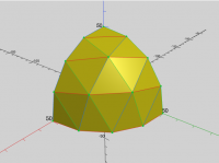
Here is the logic which works according to me:
[image: Screenshot 2026-07-02 at 10.40.52 PM.png]
On Thu, 2 Jul 2026 at 19:24, Revar Desmera via Discuss <
discuss@lists.openscad.org> wrote:
On Jul 2, 2026, at 4:54 AM, Adrian Mariano via Discuss <
Revar, it doesn't look like _make_octa_sphere depends deeply on library
code---really just one cumsum call.
cumsum(), zrot(), zflip(), select(), flatten(), quantup(), segs()...
Yeah, okay, not as bad as I first thought. When I skimmed the code, I
kind of assumed it was going to end up using vnf_tri_array() and
vnf_merge(). I forgot I optimized those out before.
For those who just want the conceptual framework for how to do octa
spheres, it boils down to:
- Calculate how many vertices the sphere should have around the equator
(segs). This must be modulo 4, as we are going to triangulate one
spherical triangle and copy it 8 times (4 quadrants, top and bottom).
- subdivs = segs / 4
- Assuming that the three corners of the spherical triangle are on the X+
axis, the Y+ axis, and the Z+ axis, subdivide the three edges of the
spherical triangle by rotating a vector from each of the corner points
toward its neighbor corner by 90/subdiv degree steps. You now have all the
edge vertices.
- Take pairs of edges, and iterate their "rows" of vertices, so that you
get a related vertex from both edges.
- Get the axis of the greater circle that the two edge vertices are on.
(cross product)
- Subdivide that greater circle by the appropriate number of interior
vertices for that "row" by rotating between the edge vertices on the
greater circle axis. slerp() may have been involved.
- Do this for every possible pair of edges. This gets you three sets of
interior points that are slightly off from each other.
- Average the three sets of interior point vectors and normalize them.
You now have all the vertices for each subdivided octa "face".
- Copy this triangle (excluding duplicate vertices) rotating them by 0,
90, 180, and 270 degrees.
- Copy this full set of "top" vertices, flipping across the XY plane to
get the "bottom"vertices. (excluding duplicate vertices again)
- Calculate faces between the vertices.
At least, that's how I remember it working.
OpenSCAD mailing list
To unsubscribe send an email to discuss-leave@lists.openscad.org
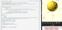
Here is the logic which works according to me:
[image: Screenshot 2026-07-02 at 10.40.52 PM.png]
On Thu, 2 Jul 2026 at 19:24, Revar Desmera via Discuss <
discuss@lists.openscad.org> wrote:
>
>
> > On Jul 2, 2026, at 4:54 AM, Adrian Mariano via Discuss <
> discuss@lists.openscad.org> wrote:
> >
> > Revar, it doesn't look like _make_octa_sphere depends deeply on library
> code---really just one cumsum call.
> >
>
> cumsum(), zrot(), zflip(), select(), flatten(), quantup(), segs()...
> Yeah, okay, not as bad as I first thought. When I skimmed the code, I
> kind of assumed it was going to end up using vnf_tri_array() and
> vnf_merge(). I forgot I optimized those out before.
>
> For those who just want the conceptual framework for how to do octa
> spheres, it boils down to:
>
> 1) Calculate how many vertices the sphere should have around the equator
> (segs). This must be modulo 4, as we are going to triangulate one
> spherical triangle and copy it 8 times (4 quadrants, top and bottom).
> 2) subdivs = segs / 4
> 3) Assuming that the three corners of the spherical triangle are on the X+
> axis, the Y+ axis, and the Z+ axis, subdivide the three edges of the
> spherical triangle by rotating a vector from each of the corner points
> toward its neighbor corner by 90/subdiv degree steps. You now have all the
> edge vertices.
> 4) Take pairs of edges, and iterate their "rows" of vertices, so that you
> get a related vertex from both edges.
> 5) Get the axis of the greater circle that the two edge vertices are on.
> (cross product)
> 6) Subdivide that greater circle by the appropriate number of interior
> vertices for that "row" by rotating between the edge vertices on the
> greater circle axis. slerp() may have been involved.
> 7) Do this for every possible pair of edges. This gets you three sets of
> interior points that are slightly off from each other.
> 8) Average the three sets of interior point vectors and normalize them.
> You now have all the vertices for each subdivided octa "face".
> 9) Copy this triangle (excluding duplicate vertices) rotating them by 0,
> 90, 180, and 270 degrees.
> 10) Copy this full set of "top" vertices, flipping across the XY plane to
> get the "bottom"vertices. (excluding duplicate vertices again)
> 11) Calculate faces between the vertices.
>
> At least, that's how I remember it working.
>
> - Revar
> _______________________________________________
> OpenSCAD mailing list
> To unsubscribe send an email to discuss-leave@lists.openscad.org
RD
Revar Desmera
Thu, Jul 2, 2026 5:52 PM
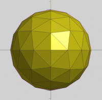
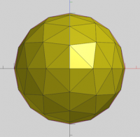
Maybe it's just the orientation of your screenshot, but those triangle faces look oddly proportioned. For reference, here's what the BOSL2 code generates. We're fairly sure this is the optimal vertex placement, because the faces on the complete sphere look identical from the Top, Left, and Front views.


cumsum(), zrot(), zflip(), select(), flatten(), quantup(), segs()...
Yeah, okay, not as bad as I first thought. When I skimmed the code, I kind of assumed it was going to end up using vnf_tri_array() and vnf_merge(). I forgot I optimized those out before.
For those who just want the conceptual framework for how to do octa spheres, it boils down to:
- Calculate how many vertices the sphere should have around the equator (segs). This must be modulo 4, as we are going to triangulate one spherical triangle and copy it 8 times (4 quadrants, top and bottom).
- subdivs = segs / 4
- Assuming that the three corners of the spherical triangle are on the X+ axis, the Y+ axis, and the Z+ axis, subdivide the three edges of the spherical triangle by rotating a vector from each of the corner points toward its neighbor corner by 90/subdiv degree steps. You now have all the edge vertices.
- Take pairs of edges, and iterate their "rows" of vertices, so that you get a related vertex from both edges.
- Get the axis of the greater circle that the two edge vertices are on. (cross product)
- Subdivide that greater circle by the appropriate number of interior vertices for that "row" by rotating between the edge vertices on the greater circle axis. slerp() may have been involved.
- Do this for every possible pair of edges. This gets you three sets of interior points that are slightly off from each other.
- Average the three sets of interior point vectors and normalize them. You now have all the vertices for each subdivided octa "face".
- Copy this triangle (excluding duplicate vertices) rotating them by 0, 90, 180, and 270 degrees.
- Copy this full set of "top" vertices, flipping across the XY plane to get the "bottom"vertices. (excluding duplicate vertices again)
- Calculate faces between the vertices.
At least, that's how I remember it working.
OpenSCAD mailing list
To unsubscribe send an email to discuss-leave@lists.openscad.org mailto:discuss-leave@lists.openscad.org
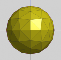
Maybe it's just the orientation of your screenshot, but those triangle faces look oddly proportioned. For reference, here's what the BOSL2 code generates. We're fairly sure this is the optimal vertex placement, because the faces on the complete sphere look identical from the Top, Left, and Front views.


- Revar
> On Jul 2, 2026, at 10:13 AM, Sanjeev Prabhakar <sprabhakar2006@gmail.com> wrote:
>
> Here is the logic which works according to me:
> <Screenshot 2026-07-02 at 10.40.52 PM.png>
>
> On Thu, 2 Jul 2026 at 19:24, Revar Desmera via Discuss <discuss@lists.openscad.org <mailto:discuss@lists.openscad.org>> wrote:
>>
>>
>> > On Jul 2, 2026, at 4:54 AM, Adrian Mariano via Discuss <discuss@lists.openscad.org <mailto:discuss@lists.openscad.org>> wrote:
>> >
>> > Revar, it doesn't look like _make_octa_sphere depends deeply on library code---really just one cumsum call.
>> >
>>
>> cumsum(), zrot(), zflip(), select(), flatten(), quantup(), segs()...
>> Yeah, okay, not as bad as I first thought. When I skimmed the code, I kind of assumed it was going to end up using vnf_tri_array() and vnf_merge(). I forgot I optimized those out before.
>>
>> For those who just want the conceptual framework for how to do octa spheres, it boils down to:
>>
>> 1) Calculate how many vertices the sphere should have around the equator (segs). This must be modulo 4, as we are going to triangulate one spherical triangle and copy it 8 times (4 quadrants, top and bottom).
>> 2) subdivs = segs / 4
>> 3) Assuming that the three corners of the spherical triangle are on the X+ axis, the Y+ axis, and the Z+ axis, subdivide the three edges of the spherical triangle by rotating a vector from each of the corner points toward its neighbor corner by 90/subdiv degree steps. You now have all the edge vertices.
>> 4) Take pairs of edges, and iterate their "rows" of vertices, so that you get a related vertex from both edges.
>> 5) Get the axis of the greater circle that the two edge vertices are on. (cross product)
>> 6) Subdivide that greater circle by the appropriate number of interior vertices for that "row" by rotating between the edge vertices on the greater circle axis. slerp() may have been involved.
>> 7) Do this for every possible pair of edges. This gets you three sets of interior points that are slightly off from each other.
>> 8) Average the three sets of interior point vectors and normalize them. You now have all the vertices for each subdivided octa "face".
>> 9) Copy this triangle (excluding duplicate vertices) rotating them by 0, 90, 180, and 270 degrees.
>> 10) Copy this full set of "top" vertices, flipping across the XY plane to get the "bottom"vertices. (excluding duplicate vertices again)
>> 11) Calculate faces between the vertices.
>>
>> At least, that's how I remember it working.
>>
>> - Revar
>> _______________________________________________
>> OpenSCAD mailing list
>> To unsubscribe send an email to discuss-leave@lists.openscad.org <mailto:discuss-leave@lists.openscad.org>
JB
Jordan Brown
Thu, Jul 2, 2026 6:37 PM
On 7/2/2026 3:30 AM, Leonard Martin Struttmann via Discuss wrote:
First, never set $fn at the top level like this, except maybe for
specific demonstrations. Use $fs and $fa,...
I've seen statements like this several times. However, understanding
$fn is easy. I have a hard time grasping how to actually use $fa and
$fs together. Is there some sort of guide that gives example values
for various situations?
The simple answer is: set $fa and $fs both to 1, and never think about
it again. If you're really picky about your circles, set $fs to 0.5.
$fa controls the minimum angle of one "wedge" of the circle. (Or,
equivalently, the angle between one side and the next.) $fa=1 means that
a single wedge will never be smaller than one degree. Mostly this
controls large circles; it means that even a very large circle will be
limited to 360 sides. For large circles, you don't need sides smaller
than a certain size because the angle between one side and the next is
too small to see or feel.
$fs controls the minimum size of one side of the circle. $fs=1 means
that a single side will never be smaller than one unit (typically, one
millimeter). Mostly this controls small circles; no matter how small
the circle its sides will not be smaller than 1 unit, down to a minimum
of five sides. For small circles, you don't need sides smaller than a
certain size because they would be too small to see, or might even be
smaller than the precision of your printer.
(How large is "large"? How small is "small"? Solving the equations,
for $fs and $fa set to 1 "large" is larger than about 60mm radius. For
$fs=0.5 and $fa=1, "large" is larger than about 29mm radius.)
Note:
- If you look at the math in detail it turns out that it's a little
bit wrong. You can end up with angles slightly less than $fa or
sides slightly less than $fs. Except for wanting the description to
be precisely correct the difference isn't important.
If you want to fine tune a bit:
- You might set $fa to 2. My experiments indicate that it is
difficult to see the sides and vertexes of even a large circle with
2° wedges.
- You might set $fs to 0.5. Some people think that the sides are
still too coarse at 1mm.
But I find that $fa=1/$fs=1 produces results that I'm happy with, and
it's easy to remember.
Caveats:
- If you're trying to test these with prints - as you should - make
sure that your slicer's arc fitting feature, if any, is disabled.
- If you have a really shiny finish, the sides may be more visible
through reflections as you turn the object.
- Material may matter. If you're lucky enough to be printing in
metal, I suspect you'll need more sides.
- Nozzle size may matter. Basically all of my experience is with
0.4mm nozzles; I would expect that smaller nozzles would produce
sharper vertexes and so might need more sides.
- Do not use the display as an indication of whether your sides are
small enough. You can see sides on the display that are invisible
in an actual print.
All of those apply to $fn too.
- Could someone explain this line from the OpenSCAD documentation:
"The number of line segments for a cylinder is determined using the
greater of the two radii."
What radii? As a user I am specifying the radius of the cylinder.
I've updated this to say:
If a cylinder has both top and bottom radii specified, the number of
line segments is determined using the greater of the two.
The description at cylinder() itself is a bit clearer. It has just
described the r, r1, and r2 parameters, and says:
The resolution of a cylinder is based on its radius and the $fa, $fs
and $fn variables. For a cone, the resolution is based on the radius
of the larger end. For more information on these special variables
see Circle resolution: $fa, $fs, and $fn.
On 7/2/2026 3:30 AM, Leonard Martin Struttmann via Discuss wrote:
>> First, never set $fn at the top level like this, except maybe for
>> specific demonstrations. Use $fs and $fa,...
> I've seen statements like this several times. However, understanding
> $fn is easy. I have a hard time grasping how to actually use $fa and
> $fs together. Is there some sort of guide that gives example values
> for various situations?
The simple answer is: set $fa and $fs both to 1, and never think about
it again. If you're really picky about your circles, set $fs to 0.5.
$fa controls the minimum angle of one "wedge" of the circle. (Or,
equivalently, the angle between one side and the next.) $fa=1 means that
a single wedge will never be smaller than one degree. Mostly this
controls large circles; it means that even a very large circle will be
limited to 360 sides. For large circles, you don't need sides smaller
than a certain size because the angle between one side and the next is
too small to see or feel.
$fs controls the minimum size of one side of the circle. $fs=1 means
that a single side will never be smaller than one unit (typically, one
millimeter). Mostly this controls small circles; no matter how small
the circle its sides will not be smaller than 1 unit, down to a minimum
of five sides. For small circles, you don't need sides smaller than a
certain size because they would be too small to see, or might even be
smaller than the precision of your printer.
(How large is "large"? How small is "small"? Solving the equations,
for $fs and $fa set to 1 "large" is larger than about 60mm radius. For
$fs=0.5 and $fa=1, "large" is larger than about 29mm radius.)
Note:
* If you look at the math in detail it turns out that it's a little
bit wrong. You can end up with angles slightly less than $fa or
sides slightly less than $fs. Except for wanting the description to
be precisely correct the difference isn't important.
If you want to fine tune a bit:
* You might set $fa to 2. My experiments indicate that it is
difficult to see the sides and vertexes of even a large circle with
2° wedges.
* You might set $fs to 0.5. Some people think that the sides are
still too coarse at 1mm.
But I find that $fa=1/$fs=1 produces results that I'm happy with, and
it's easy to remember.
Caveats:
* If you're trying to test these with prints - as you should - make
sure that your slicer's arc fitting feature, if any, is disabled.
* If you have a really shiny finish, the sides may be more visible
through reflections as you turn the object.
* Material may matter. If you're lucky enough to be printing in
metal, I suspect you'll need more sides.
* Nozzle size may matter. Basically all of my experience is with
0.4mm nozzles; I would expect that smaller nozzles would produce
sharper vertexes and so might need more sides.
* Do not use the display as an indication of whether your sides are
small enough. You can see sides on the display that are invisible
in an actual print.
All of those apply to $fn too.
> 2. Could someone explain this line from the OpenSCAD documentation:
>
> "The number of line segments for a cylinder is determined using the
> greater of the two radii."
>
> What radii? As a user I am specifying the radius of the cylinder.
I've updated this to say:
If a cylinder has both top and bottom radii specified, the number of
line segments is determined using the greater of the two.
The description at cylinder() itself is a bit clearer. It has just
described the r, r1, and r2 parameters, and says:
The resolution of a cylinder is based on its radius and the $fa, $fs
and $fn variables. For a cone, the resolution is based on the radius
of the larger end. For more information on these special variables
see Circle resolution: $fa, $fs, and $fn.
JB
Jordan Brown
Thu, Jul 2, 2026 6:56 PM
On 7/2/2026 8:40 AM, larry via Discuss wrote:
sphere(101);
Bounding box:
Min: -101.00, -100.45, -100.45
Max: 101.00, 100.45, 100.45
Size: 202.00, 200.89, 200.89
Rendering finished.
This is because for those particular parameters the +Y and -Y poles are
truncated. With default $fa/$fs/$fn, you get a 30-gon, which is not a
multiple of 4.
I think that centering problems can only happen in the X axis, that in
Y and Z everything is always symmetric. It happens when the circle has
an odd number of sides.
X-axis centering is easy to see for "circles" with small odd numbers of
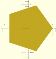
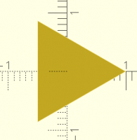
sides:
Here's a three-sided circle with a radius of 1. Note that it protrudes
a great deal more +X than -X, and so in a sense is not centered.
The effect is not as pronounced for a five-sided circle, but it's still
there:
You can also see the Y-axis truncation in both figures. The theoretical
circle extends further than the top and bottom vertexes.
On 7/2/2026 8:40 AM, larry via Discuss wrote:
> sphere(101);
>
> Bounding box:
> Min: -101.00, -100.45, -100.45
> Max: 101.00, 100.45, 100.45
> Size: 202.00, 200.89, 200.89
> Rendering finished.
This is because for those particular parameters the +Y and -Y poles are
truncated. With default $fa/$fs/$fn, you get a 30-gon, which is not a
multiple of 4.
I *think* that centering problems can only happen in the X axis, that in
Y and Z everything is always symmetric. It happens when the circle has
an odd number of sides.
X-axis centering is easy to see for "circles" with small odd numbers of
sides:
Here's a three-sided circle with a radius of 1. Note that it protrudes
a great deal more +X than -X, and so in a sense is not centered.
The effect is not as pronounced for a five-sided circle, but it's still
there:
You can also see the Y-axis truncation in both figures. The theoretical
circle extends further than the top and bottom vertexes.
L
larry
Thu, Jul 2, 2026 8:03 PM
On Thu, 2026-07-02 at 11:56 -0700, Jordan Brown wrote:
On 7/2/2026 8:40 AM, larry via Discuss wrote:
sphere(101);
Bounding box:
Min: -101.00, -100.45, -100.45
Max: 101.00, 100.45, 100.45
Size: 202.00, 200.89, 200.89
Rendering finished.
This is because for those particular parameters the +Y and -Y
poles > are truncated. With default $fa/$fs/$fn, you get a 30-gon,
which is > not a multiple of 4.
I think that centering problems can only happen in the X axis, >
that in Y and Z everything is always symmetric. It happens when
the > circle has an odd number of sides.
I have definitely seen centring problems in the Y axis, though it isn't
nearly as obvious as your three-sided circle. The difference is usually
something small, say something like this (didn't look any up, just a
approximation to show the amount). Ymax: 104.83 Ymin: 105.00
X-axis centering is easy to see for "circles" with small odd
numbers > of sides:
Here's a three-sided circle with a radius of 1. Note that it >
protrudes a great deal more +X than -X, and so in a sense is not >
centered.
The effect is not as pronounced for a five-sided circle, but it's
You can also see the Y-axis truncation in both figures. The >
theoretical circle extends further than the top and bottom
vertexes.
On Thu, 2026-07-02 at 11:56 -0700, Jordan Brown wrote:
> > On 7/2/2026 8:40 AM, larry via Discuss wrote:
> >
> > > > sphere(101);
> > > >
> > > > Bounding box:
> > > > Min: -101.00, -100.45, -100.45
> > > > Max: 101.00, 100.45, 100.45
> > > > Size: 202.00, 200.89, 200.89
> > > > Rendering finished.
> >
> >
> > This is because for those particular parameters the +Y and -Y
> > poles > are truncated. With default $fa/$fs/$fn, you get a 30-gon,
> > which is > not a multiple of 4.
> >
> >
> > I *think* that centering problems can only happen in the X axis, >
> > that in Y and Z everything is always symmetric. It happens when
> > the > circle has an odd number of sides.
I have definitely seen centring problems in the Y axis, though it isn't
nearly as obvious as your three-sided circle. The difference is usually
something small, say something like this (didn't look any up, just a
approximation to show the amount). Ymax: 104.83 Ymin: 105.00
> > X-axis centering is easy to see for "circles" with small odd
> > numbers > of sides:
> >
> >
> > Here's a three-sided circle with a radius of 1. Note that it >
> > protrudes a great deal more +X than -X, and so in a sense is not >
> > centered.
> >
> > The effect is not as pronounced for a five-sided circle, but it's
> > > still there:
> > You can also see the Y-axis truncation in both figures. The >
> > theoretical circle extends further than the top and bottom
> > vertexes.
> >
> >
> >
> >
JB
Jordan Brown
Thu, Jul 2, 2026 8:15 PM
On 7/2/2026 9:01 AM, larry via Discuss wrote:
OpenSCAD built-in spheres always have their +Z and -Z poles
truncated.
If $fn is a multiple of 2 but not a multiple of 4, they also have
their +Y and -Y poles truncated.
If $fn is not even a multiple of 2, it also has its -X pole
truncated. (And the +Y/-Y poles are truncated differently.)
Yes, and if I want to see what the actual size and position of a sphere
(for example) is, I set $fn to 360.
Which gets you correct positions on X and Y, but so does $fn=4. It's
the multiple-of-4 part that gets X and Y correct.
The Z positions are still slightly off, no matter the $fn, because they
are always off, sigh.
I usually set the top $fn as
$fn=$preview ? 60 : 180;
If you build a 10mm-diameter circle with $fn=180, you'll end up with
0.17mm sides. Your printer's XY resolution is probably only 0.1mm.
My experiments indicate that for a 10mm-diameter circle, a 20-gon has
near-invisible sides. $fa=1/$fs=1 yields 32 sides; at that level I
can't see them.
The advantage of using $fs/$fa is that you end up with reasonable
numbers of sides for all sizes of circles, without having to think about it.
This is all a lot less important than it used to be. Manifold is so
much faster that we don't see "Why does this take so long to render?" /
"Your spheres have way too many sides" very often.
Still, it adds up. I was drawing something where I was using $fn to
control the precision of a curve, and was using circles to mark the
points on the curve, without thinking about the fact that the circles
were affected by $fn too, and performance started to suffer.
Data point: For my system (i7-13700), with $fn=180, rendering 125 r=2
spheres takes about 20s. r=2 only really needs about $fn=13, maybe 26
at the most. With $fn=26 (or $fa=1, $fs=0.5), those 125 spheres take
less than half a second.
Anyhow, this horse is pretty dead so I'll try to stop flogging it.
On 7/2/2026 9:01 AM, larry via Discuss wrote:
>> OpenSCAD built-in spheres always have their +Z and -Z poles
>> truncated.
>> If $fn is a multiple of 2 but not a multiple of 4, they also have
>> their +Y and -Y poles truncated.
>> If $fn is not even a multiple of 2, it also has its -X pole
>> truncated. (And the +Y/-Y poles are truncated differently.)
> Yes, and if I want to see what the actual size and position of a sphere
> (for example) is, I set $fn to 360.
Which gets you correct positions on X and Y, but so does $fn=4. It's
the multiple-of-4 part that gets X and Y correct.
The Z positions are still slightly off, no matter the $fn, because they
are *always* off, sigh.
> I usually set the top $fn as
> $fn=$preview ? 60 : 180;
If you build a 10mm-diameter circle with $fn=180, you'll end up with
0.17mm sides. Your printer's XY resolution is probably only 0.1mm.
My experiments indicate that for a 10mm-diameter circle, a 20-gon has
near-invisible sides. $fa=1/$fs=1 yields 32 sides; at that level I
can't see them.
The advantage of using $fs/$fa is that you end up with reasonable
numbers of sides for all sizes of circles, without having to think about it.
This is all a lot less important than it used to be. Manifold is so
much faster that we don't see "Why does this take so long to render?" /
"Your spheres have way too many sides" very often.
Still, it adds up. I was drawing something where I was using $fn to
control the precision of a curve, and was using circles to mark the
points on the curve, without thinking about the fact that the circles
were affected by $fn too, and performance started to suffer.
Data point: For my system (i7-13700), with $fn=180, rendering 125 r=2
spheres takes about 20s. r=2 only really needs about $fn=13, maybe 26
at the most. With $fn=26 (or $fa=1, $fs=0.5), those 125 spheres take
less than half a second.
Anyhow, this horse is pretty dead so I'll try to stop flogging it.